Sunday, June 14, 2026

Introduction to Electronics Components

 Resistors


          A resistor is a component of an electrical circuit that resists the flow of electrical current. A resistor has two terminals across which electricity must pass, and is designed to drop the voltage of the current as it flows from one terminal to the next. A resistor is primarily used to create and maintain a known safe current within an electrical component.
 

                    Physical Structure                                                                            Symbol                                                                                                                                                                     
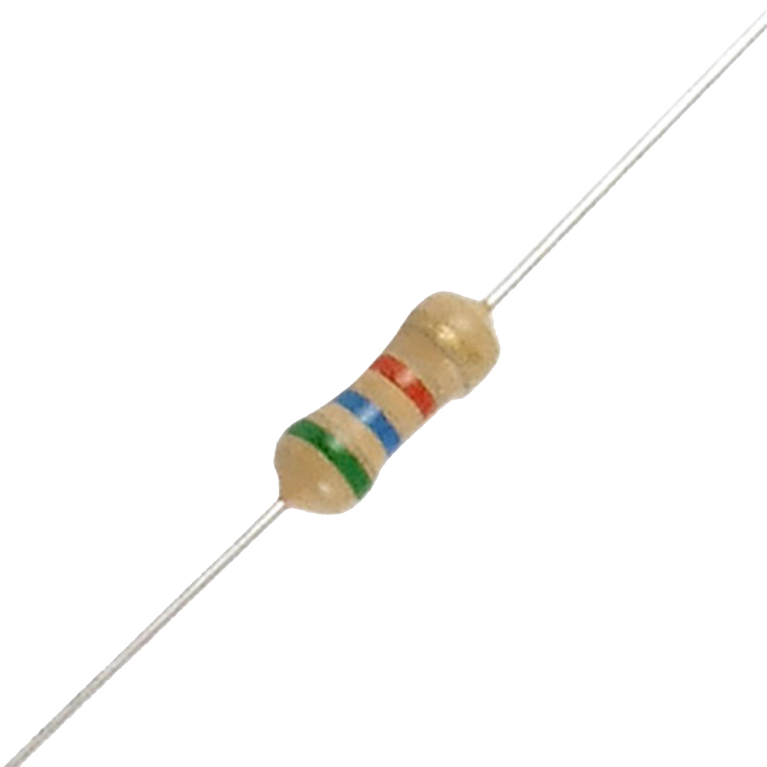
  1. FIXED VALUE RESISTOR       (Resistor Color Code Chart)     
 
Band Color
Options
Band 1
position No
Band 2
position No

        Band 3
Multiplier Value
Band 4
Value Tolerance
Black
 0
0

×10°                                
---
Brown
1
1

×10¹
± 1%
Red
2
2

×10²
± 2%
Orange
3
3

×10³
---
Yellow
4
4

               ×10
----
Green
5
5

              ×10
± 0.5%
Blue
6
6

              ×10
± 0.25%
Violet
7
7

--
± 0.1%
Gray
8
8

--
± 0.05%
White
9
9

--
----
None
--
--

--
           ± 20%
Silver
--
--

× 0.1
           ± 10%
Gold
--
--

× 0.01
           ± 5%


Example:- (Measurement process)  -Most resistors have 4 bands:
  • The first band gives the first digit.
  • The second band gives the second digit.
  • The third band indicates the number of zeros.
  • The fourth band is used to show the tolerance (precision) of the resistor 


Calculation

First Band

Second Band

Third Band

Fourth Band

Calculated Value

Color Name

Position Value

Red            Violet       Green         Silver

2                  7               105              +10%

2700000W +10%

2.7MW +10%


Resistor

Calculation

First Band

Second Band

Third Band

Fourth Band

Calculated Value

Measurement Value by Digital Multimeter

Sample #1

Color Name

Position Value


Sample #2

Color Name

Position Value


Sample #3

Color Name

Position Value


 B.VARIABLE RESISTOR  

      There are two types of variable resistors


1. Potentiometer                                                                                        2. Preset


Variable resistors consist of a resistance track with connections at both ends and a wiper which moves along the track as you turn the spindle. The track may be made from carbon, cermet (ceramic and metal mixture) or a coil of wire (for low resistances). The track is usually rotary but straight track versions, usually called sliders, are also available.
Variable resistors may be used as a potentiometer with all three connections in use. Miniature versions called presets are made for setting up circuits which will not require further adjustment. Variable resistors are often called potentiometers in books and catalogues. They are specified by their maximum resistance, linear or logarithmic track,  their physical size. The standard spindle diameter is 6mm.
Physical Structure:


                                                Potentiometer                                   Preset


Linear (LIN) track means that the resistance changes at a constant rate as you move the wiper.
Logarithmic (LOG) track means that the resistance changes slowly at one end of the track and rapidly at the other end, so halfway along the track is not half the total resistance! This arrangement is used for volume (loudness) controls because the human ear has a logarithmic response to loudness so fine control (slow change) is required at low volumes and coarser control (rapid change) at high volumes
Function :-Resistor has a lot of functions.  The resistor has function of current limiting and voltage drop. when used with other devices like capacitors and inductors it can have a vast variety of functions depending upon in which configuration it is used.
Potentiometer are used for voltage dividing purpose.
Specification :-         1. Power Rating (W)      2. Resistive Value (Ω  Value)
     The Resistor Power Rating is sometimes called the Resistors Wattage Rating and is defined as the amount of heat that a resistive element can dissipate for an indefinite period of time without degrading its performance. Every resistor has a maximum power rating which is determined by its physical size as generally, the greater its surface area the more power it can dissipate safely into the ambient air or into a heat sink

  Resistors are rated by the value of their resistance ( Ω  Value)


Standard Value (Written on the Device Surface)

The measured value by Multimeter (between two end terminals)

Potentiometer


Preset


CAPACITORS
  A capacitor is a passive electronic component that stores energy in the form of an electrostatic field.  In its simplest form, a capacitor consists of two conducting plates separated by an insulating material called the dielectric.  Capacitance is directly proportional to the surface areas of the plates, and is inversely proportional to the plates' separation. Capacitance also depends on the dielectric constant of the dielectric material separating the plates.
There are two types of capacitor

Polarised (Electrolytic Capacitors , Value Above 1uF   


 Circuit Symbol                                                           Physical Structure

A type of capacitor in which one plate is coated through electrolysis with an oxide to serve as the dielectric, while the other plate is replaced by an electrolyte. Electrolytic capacitors can achieve very high capacitance (>1uF) with very small sizes, but only act as capacitors as long as the current flows in one direction.

 Measurement Value:-- Its capacitance value(uF) and voltage level is given on the surface 

Unpolarised (Non- Electrolytic) Small Value below 1uF)


Circuit Symbol                                                            Physical structure
It has no electrical polarization. So in any direction you can use or measure. 
Capacitor Number Code(for non electrolytic)
A number code is often used on small capacitors where printing is difficult:      
·         the 1st number is the 1st digit,
·         the 2nd number is the 2nd digit,
·         the 3rd number is the number of zeros to give the capacitance in pF.
·         Ignore any letters - they just indicate tolerance and voltage rating.
       
For example:   102   means 1000pF = 1nF   (not 102pF!)
If there is no third digit(only two digit),then specified number is the capacitive value in pF. 
Three prefixes (multipliers) are used, µ (micro), n (nano) and p (pico):
  • µ means 10-6 (millionth), so 1000000µF = 1F
  • n means 10-9 (thousand-millionth), so 1000nF = 1µF
  • p means 10-12 (million-millionth), so 1000pF = 1nF

Variable capacitors       1. Gang Capacitor       2.Trimmer Capacitor

Its maximum Value is given on the surface

1. Gang Capacitor:A combination of two or more variable capacitors mounted on a common shaft to permit adjustment by a single control.


     Symbol                                                                            Physical Structure

2. Trimmer Capacitors:Trimmer capacitors (trimmers) are miniature variable capacitors. They are designed to be mounted directly onto the circuit board and adjusted only when the circuit is built. Trimmer capacitors are only available with very small capacitances, normally less than 100pF


Symbol                                                                                    Physical Structure                                                          

Specification of capacitor

1.      Voltage Rating: All capacitors have a voltage rating. This tells you how much voltage the dielectric (insulator) can withstand before allowing DC to pass between its plates

2.      Capacitor’s Rating:- The capacitance rating is there because the energy stored in a capacitor is W = 1/2CV2, where W is the stored energy in joules, C is the capacitance rating in farads, and V is the voltage on the cap. The cap's capacitance is a necessary specification because circuit design and performance hinge on having caps the correct value for the configuration of the circuit.


Function :-    A capacitor stores electric charge. A capacitor is used with a resistor in a timing circuit. It can also be used as a filter, to block DC signals but pass AC signals


Standard Value (Written on the Device Surface)

The measured Value by LCR meter

Capacitor #1


Capacitor #2


DIODE


       When a P-type semiconductor are diffused  in a N-type semiconductor in such a way that the contact surface is called diode.  A diode is a specialized electronic component with two electrodes called the anode and the cathode. Most diodes are made with semiconductor materials such as silicon, germanium, or selenium. The fundamental property of a diode is its tendency to conduct electric current in only one direction. When the cathode is negatively charged relative to the anode at a voltage greater than a certain minimum called forward breakover, then current flows through the diode. If the cathode is positive with respect to the anode, is at the same voltage as the anode, or is negative by an amount less than the forward breakover voltage, then the diode does not conduct current. This is a simplistic view. The forward break over voltage is approximately six tenths of a volt (0.6 V) for silicon devices, 0.3 V for germanium devices, and 1 V for selenium devices.


Symbol

Type of diode
There are many different types of diodes that are available for use in electronics design. But most useful diodes in our laboratory are
A. PN junction diode   B. Zener Diode       C. Light Emitting Diode(LED)
A. PN junction diode  :-  It is also two type, one is Germanium diode (Ge) and other is Silicon diode(Si).
If we join a section of N-type semiconductor material with a similar section of P-type semiconductor material, we obtain a device known as a PN JUNCTION. The diode is nothing more than a two-element semiconductor device that makes use of the rectifying properties of a PN junction to convert alternating current into direct current by permitting current flow in only one direction.

Testing diodes:- (By using DMM(Digital Multimeter)

Set your meter to the diode test mode. Connect the red meter lead to the one terminal of diode. Connect the black meter lead to the other terminal and then reverse the meter leads . If a good diode will read a JUNCTION DROP voltage of between .25V and .7V in one direction (.3V for Ge diode and .7 for Si diode in forward break over voltage ). And other direction will show open or overload (OL).  If both the direction showing OL or showing same voltage, then the diode is faulty. Normally the reverse break down voltage is high in case of Si or Ge. So we cannot test the reverse break down voltage  by DMM.

In Zener diode testing is similar to the silicon diode testing.

Zener diode :-

Zener diodes are used to maintain a fixed voltage. They are designed to 'breakdown' in a reliable and non-destructive way so that they can be used in reverse to maintain a fixed voltage across their terminals.They are connected with a resistor in series to limit the current.


Zener diodes can be distinguished from ordinary diodes by their code and breakdown voltage which are printed on them. Zener diode codes begin BZX... or BZY... Their breakdown voltage is printed with V in place of a decimal point, so 4V7 means 4.7V for example.
Zener diodes are rated by their breakdown voltage and maximum power.
 Light Emitting Diodes (LEDs)
A light-emitting diode (LED) is a semiconductor device that emits visible light when an electric current passes through it. The light is not particularly bright, but in most LEDs it is monochromatic, occurring at a single wavelength. The output from an LED can range from red (at a wavelength of approximately 700 nanometers) to blue-violet (about 400 nanometers). Some LEDs emit infrared (IR) energy (830 nanometers or longer); such a device is known as an infrared-emitting diode (IRED).


Typical values of forward voltage are:

IR: 1.2 V, Red: 1.85 V, Yellow: 2 V, Green: 2.15 V. The new blue LEDs will be somewhat higher (perhaps 3 V). These voltages are at reasonable forward current. Depending on the actual technology (i.e., compounds like GaAsP, GaP, GaAsP/GaP, GaAlAs, etc.),

The LED consists of a chip of semiconducting material doped with impurities to create a p-n junction. As in other diodes, current flows easily from the p-side, or anode, to the n-side, or cathode, but not in the reverse direction. Charge-carriers—electrons and holes—flow into the junction from electrodes with different voltages. When an electron meets a hole, it falls into a lower energy level, and releases energy in the form of a photon.

The wavelength of the light emitted, and thus its color depends on the band gap energy of the materials forming the p-n junction. In silicon or germanium diodes, the electrons and holes recombine by a non-radiative transition, which produces no optical emission, because these are indirect band gap materials. The materials used for the LED have a direct band gap with energies corresponding to near-infrared, visible, or near-ultraviolet light


Symbol

Device Number

Forward Voltage Drop

Reverse Voltage Drop

Silicon Diode


Zener Diode


LED (Specify the Color)


** Mention the different applications of diodes.

Diode specifications characteristics and parameters:-

The list below provides details of the various diode characteristics, and diode parameters found in the datasheets and specifications for diodes according to their Number specified on the device surface.
  • Semiconductor material:  
  • Forward voltage drop (Vf):  
  • Peak Inverse Voltage (PIV)
  • Maximum forward current:  
  • Leakage current
  • Junction capacitance:  
  • Package type

Diode
Maximum

Current
Maximum

Reverse

Voltage
1N4001
1A
50V
1N4002
1A
100V
1N4007
1A
1000V
1N5401
3A
100V
1N5408
3A
1000V


Technical data for LEDs
The table below shows typical technical data for some 5mm diameter round LEDs with diffused packages (plastic bodies). Only three columns are important and these are shown in bold. Please see below for explanations of the quantities.
Type
Colour
IF
max.
VF
typ.
VF
max.
VR
max.
Luminous
intensity
Viewing
angle
Wavelength
Standard
Red
30mA
1.7V
2.1V
5V
5mcd @ 10mA
60°
660nm
Standard
Bright red
30mA
2.0V
2.5V
5V
80mcd @ 10mA
60°
625nm
Standard
Yellow
30mA
2.1V
2.5V
5V
32mcd @ 10mA
60°
590nm
Standard
Green
25mA
2.2V
2.5V
5V
32mcd @ 10mA
60°
565nm
High intensity
Blue
30mA
4.5V
5.5V
5V
60mcd @ 20mA
50°
430nm
Super bright
Red
30mA
1.85V
2.5V
5V
500mcd @ 20mA
60°
660nm
Low current
Red
30mA
1.7V
2.0V
5V
5mcd @ 2mA
60°
625nm

IF max.
Maximum forward current, forward just means with the LED connected correctly.
VF typ.
Typical forward voltage, VL in the LED resistor calculation.
This is about 2V, except for blue and white LEDs for which it is about 4V.
VF max.
Maximum forward voltage.
VR max.
Maximum reverse voltage
You can ignore this for LEDs connected the correct way round.
Luminous intensity
Brightness of the LED at the given current, mcd = millicandela.
Viewing angle
Standard LEDs have a viewing angle of 60°, others emit a narrower beam of about 30°.
Wavelength
The peak wavelength of the light emitted, this determines the colour of the LED.
nm = nanometre.


Bipolar Junction Transistor(BJT)

A transistor is a semiconductor device used to amplify and switch electronic signals and power. It is composed of a semiconductor material with at least three terminals for connection to an external circuit. The transistor is an arrangement of semiconductor materials that share common physical boundaries. Materials most commonly used are silicon, gallium-arsenide, and germanium, into which impurities have been introduced by a process called “doping.


                                        Physical Structure                                                   
    Circuit Symbol                                                                                                                                                                    


    Type of transistor (PNP or NPN)

    Symbol

    Voltage C to B terminal

    Voltage B to C terminal

    Voltage C to E terminal

    Voltage E to C terminal

    Voltage B to E terminal

    Voltage E to B terminal

    BC548


    SL100


     ** Only two voltages will show forward bias diode voltage.

    There are two types of standard transistors, NPN and PNP, with different circuit symbols.
    The n-p-n junction transistor consists of two n-type semiconductors (called the emitter and collector) separated by a thin layer of p-type semiconductor (called the base).
    The p-n-p junction transistor, consisting of a thin layer of n-type semiconductor lying between two p-type semiconductors, works in the same manner, except that all polarities are reversed

    The leads are labeled base (B), collector (C) and emitter (E).

     Transistor Testing with a Digital multimeter

    Note down the transistor number which is specified on the device surface.
    Set a digital multimeter to diode test mode and Red lead is + terminal and black lead is – terminal.
    Test each pair of leads both ways (six tests in total):
    • The base-emitter (BE) junction should behave like a diode  and conduct one way only.
    • The base-collector (BC) junction should behave like a diode and conduct one way only.
    • The collector-emitter (CE) should not conduct either way.
    • You have to note  how much forward bias voltage from these six tests.
    Then conclude that the transistor is PNP or NPN

    The diagram shows how the junctions behave in an NPN transistor. The diodes are reversed in a PNP transistor but the same test procedure can be used. 


    Specification   
    Structure
    This shows the type of transistor, NPN or PNP. The polarities of the two types are different


    IC max.
    Maximum collector current.
    VCE max.
    Maximum voltage across the collector-emitter junction.
    You can ignore this rating in low voltage circuits.
    hFE
    This is the current gain (strictly the DC current gain). The guaranteed minimum value is given because the actual value varies from transistor to transistor - even for those of the same type! Note that current gain is just a number so it has no units.
    Ptot max.
    Maximum total power which can be developed in the transistor, note that a heat sink will be required to achieve the maximum rating. This rating is important for transistors operating as amplifiers, the power is roughly IC × VCE.
    Follow the device specification from the  according to the device number.


    NPN transistors
    Code
    Structure
    Case
    style
    IC
    max.
    VCE
    max.
    hFE
    min.
    Ptot
    max.
    Category
    (typical use)
    Possible
    substitutes
    BC107
    NPN
    TO18
    100mA
    45V
    110
    300mW
    Audio, low power
    BC182 BC547
    BC108
    NPN
    TO18
    100mA
    20V
    110
    300mW
    General purpose, low power
    BC108C BC183 BC548
    BC108C
    NPN
    TO18
    100mA
    20V
    420
    600mW
    General purpose, low power

    BC109
    NPN
    TO18
    200mA
    20V
    200
    300mW
    Audio (low noise), low power
    BC184 BC549
    BC182
    NPN
    TO92C
    100mA
    50V
    100
    350mW
    General purpose, low power
    BC107 BC182L
    BC182L
    NPN
    TO92A
    100mA
    50V
    100
    350mW
    General purpose, low power
    BC107 BC182
    BC547B
    NPN
    TO92C
    100mA
    45V
    200
    500mW
    Audio, low power
    BC107B
    BC548B
    NPN
    TO92C
    100mA
    30V
    220
    500mW
    General purpose, low power
    BC108B
    BC549B
    NPN
    TO92C
    100mA
    30V
    240
    625mW
    Audio (low noise), low power
    BC109
    2N3053
    NPN
    TO39
    700mA
    40V
    50
    500mW
    General purpose, low power
    BFY51
    BFY51
    NPN
    TO39
    1A
    30V
    40
    800mW
    General purpose, medium power
    BC639
    BC639
    NPN
    TO92A
    1A
    80V
    40
    800mW
    General purpose, medium power
    BFY51
    TIP29A
    NPN
    TO220
    1A
    60V
    40
    30W
    General purpose, high power

    TIP31A
    NPN
    TO220
    3A
    60V
    10
    40W
    General purpose, high power
    TIP31C TIP41A
    TIP31C
    NPN
    TO220
    3A
    100V
    10
    40W
    General purpose, high power
    TIP31A TIP41A
    TIP41A
    NPN
    TO220
    6A
    60V
    15
    65W
    General purpose, high power

    2N3055
    NPN
    TO3
    15A
    60V
    20
    117W
    General purpose, high power

    Please note: the data in this table was compiled from several sources which are not entirely consistent! Most of the discrepancies are minor, but please consult information from your supplier if you require precise data.
    PNP transistors
    Code
    Structure
    Case
    style
    IC
    max.
    VCE
    max.
    hFE
    min.
    Ptot
    max.
    Category
    (typical use)
    Possible
    substitutes
    BC177
    PNP
    TO18
    100mA
    45V
    125
    300mW
    Audio, low power
    BC477
    BC178
    PNP
    TO18
    200mA
    25V
    120
    600mW
    General purpose, low power
    BC478
    BC179
    PNP
    TO18
    200mA
    20V
    180
    600mW
    Audio (low noise), low power

    BC477
    PNP
    TO18
    150mA
    80V
    125
    360mW
    Audio, low power
    BC177
    BC478
    PNP
    TO18
    150mA
    40V
    125
    360mW
    General purpose, low power
    BC178
    TIP32A
    PNP
    TO220
    3A
    60V
    25
    40W
    General purpose, high power
    TIP32C
    TIP32C
    PNP
    TO220
    3A
    100V
    10
    40W
    General purpose, high power
    TIP32A
    Please note: the data in this table was compiled from several sources which are not entirely consistent! Most of the discrepancies are minor, but please consult information from your supplier if you require precise data.